

From Brian Schulz: Due to the popularity of the design, I get frequent requests from people seeking to build the F1 in unique ways. Günter proposed the idea of a carbon-framed F1 to me and I told him he was crazy but encouraged him nonetheless. The result is incredibly lightweight and it appears relatively true the F1 lines with some changes due to the materials available. When he shares how it paddles we will add it to this blog!
Cape Falcon F1 in Carbon, December 2019
I’m Guenter, living in Vienna/Austria. I’m 49y old, in real life I’m an engineer for a mobile telecom operator.
Since I’m mainly a sailor, I’m used to Carbon as a construction material. I’ve already done quite some stuff in Carbon and Epoxy, including molds, as well structural and visible parts. Furthermore, I’ve restored some of my older sailboats (wood, GRP). Whenever I talk about carbon- I don’t do any prepregs, just dry cloth+Epoxy resin.
Needless to say, I’ve always been weight addicted….
I’m quite a novice paddler, started last winter with the restoration of a racing kayak from the early 1960’s. In summer I chose then that I wanted an additional kayak just for cruising around, and that is what you do not want to do in a racer… 😉 At that time I had tried a Sea Kayak (made from PE), but by then already Greenland paddles in wood and … carbon (I think you guessed it).
Somehow, I fell over Cape Falcon while searching about the how, plans etc. The idea was born to build a Cape Falcon F1 in a standard shape but using modern materials instead of wood, thus combining these with the traditional construction method. Since the video building course was of no big use for my project I chose to only buy the plan from Brian.
Making molds for all framing (gunwales, stringers etc) and make my own tubing was discarded because of effort. Rectangular tubing is hard to get, extremely expensive and, in most cases, too stiff to bend them into gunwales, stringers etc.
The decision was made to go for round tubes instead. These are good value for their price, come in a large variety of diameters, are stiff but not too stiff to bend. Where a rectangular profile was needed, they will be combined together (gluing). This gluing can be side-to-side (for keel, stringers) or with spacers for gunwales.
All tubes used have a length of 2m. They are extended to their needed length with tubes of smaller diameter as connection pieces. All long tubes are filled with PU-foam to avoid water getting into once the boat is capsized.

Gunwales
Since the gunwales need to take force not only in bending, but as well in torsion to generate the rocker in the deck the connection of upper and lower gunwale member has to fulfill that requirement.
Because of different thickness of the tubes and the wood from the original plans all dimensions have to be recalculated to stick to the planned outline that shall be kept original. The double round tubing for gunwales also required the spreader and captive forms to support keeping the tubes in place.
I made 4 spreaders of these for each side, placing them in a way that they did not interfere with the places the ribs would be positioned later. The spreaders are made of some 5mm carbon sandwich I had as a leftover from a previous project.

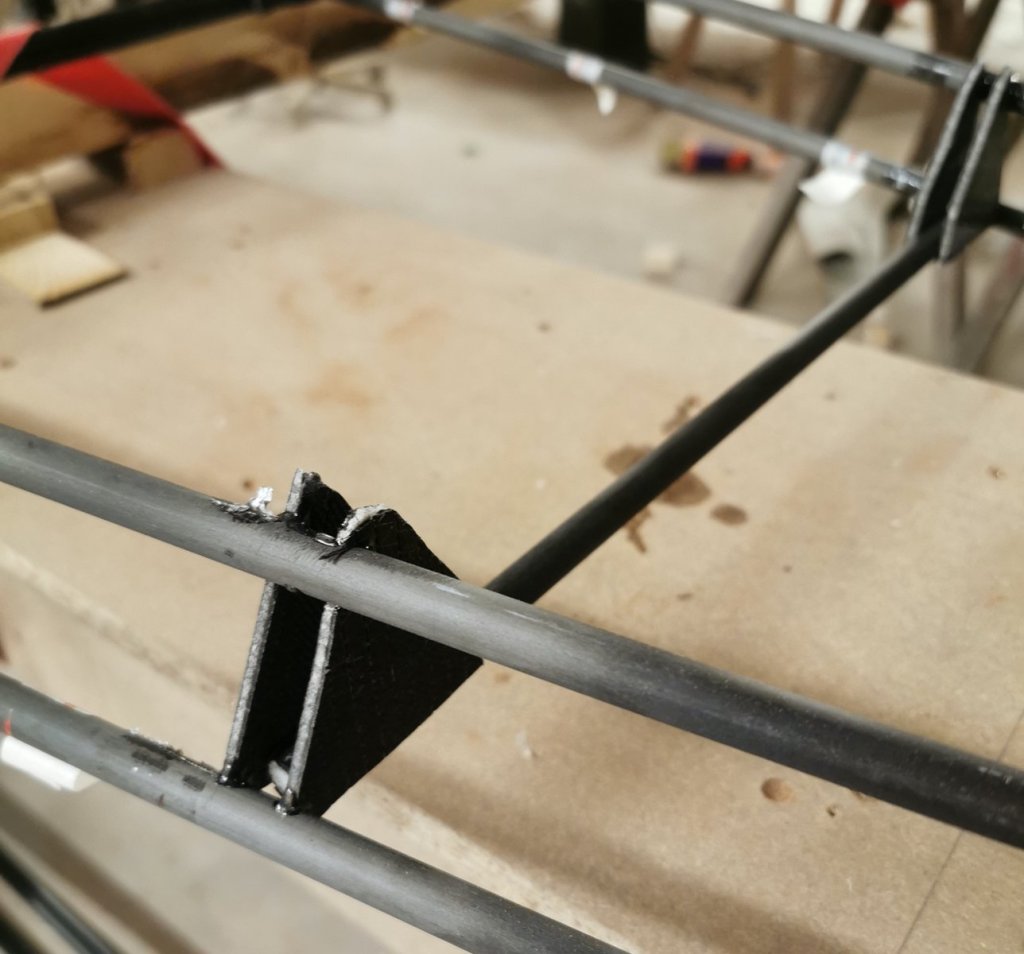
Since it is almost impossible to glue round tubes in angles in a way they can bear load all joints of gunwales and deck beams are done with carbon knees, thus enabling a solid connection and distributing the load to both of the gunwale tubes as well as keeping the gunwales in the correct angle of 65°. Later the knees were drilled through, carbon roving was led though and wrapped around the gunwales to not only rely on small bits of glue.
Deck beams
Deck beams 1-3 are bent in the original. This is not possible with carbon. I decided to do that with straight tube segments and joining them together in a way to create the geometry as in the plans.

Deck beams 3 and 4 have to bear a higher load when getting in and out the kayak. Therefore, there the tubes are doubled.

Coaming
Made over a mold cut from a 5cm Styrofoam. Sandwich of woven glass (total 5 layers at 150g/m2 each, 2 layers of foam core, pressed in vacuum bag. Then the lip is formed of Styrofoam attached with double-sided tape and glued with thickened epoxy to round inside corner.


Outside edges were rounded, then I laminated 3 overlapping layers of 200g/m2 glass over it. After that sanding and laminating with 200g/m2 carbon as visible cover. Slightly sanding to get is flat and ready to be covered while coating.

Ribs
Since the ribs will be glued to the inside of the gunwales (top tube) the lengths measured with Brian’s system have to be adapted with these correcting factors. Molds for the ribs are drawn to 5cm Styrofoam sheets, keeping the top-positions (frame width at top tube, 65° angle of gunwale), the length as well as the general shape according to Brian’s explanation (V-shaped, round, box shaped).

Roughly placed into the frame to check for matching lines. Could not be done thoroughly
because you can’t see through Styrofoam….

All 20 molds fitted together with double sided tape. Inside 2*150g/m2 woven glass, then 3mm honeycomb core. Honeycombs filled where stringers, keel etc will be placed. Outside 2-4 * 150g/m2 glass (depending onto position, thicker laminate in middle of the boat, ribs #9-13), black colored for optical reasons. All cured in steps in large vacuum bag.
To avoid sanding in between these steps were done within the bonding period of the Epoxy. I had to destroy the Styrofoam molds to get them off.
All 20 ribs together weigh 1,15kg fresh from the mold.
After that the edges were cut / sanded and the voids were filled with thickened Epoxy.

Ribs, various states 
Ribs, various states 
Ribs, various states 
Rib fresh from the mold; inside thehoneycomb is still visible
Stems for bow and stern
2cm Styrofoam. Shaped with sanding paper. Then wrapped in carbon. Edges with 400g/m2 longitudinal for increased resistance against bumps, then all with 200g/m2.


Bow and stern
Finally, I took all to the workshop of a boatbuilder where I would finish the rest.
The frame was set upside down on a bench, carefully brought to level and supported 2 times in the middle in a way that the tips of the gunwales barely touch the bed.
Gluing the bow- and stern stems to the gunwales, righting them to level and center using laser level.

With the frame still on the bench- all ribs were temporarily fixed in the frame, set to center and lining them up at keel and stringers.
When doing so I found out that my bow and stern stems were not cut to dimension…. I have missed that information in the plans. I cut them roughly and they will then finish after the frames have been glued into place permanently.
For gluing the frames, I drilled holes on both sides of keel, stringers and gunwales while still attached in aligned way. By that I can run zip-ties trough them while the glue hardens. Later I would remove these zip-ties and feed the carbon roving through them.

Ribs temporarily fixed in place 
Ribs glued to frame, keel and stringers
Stringers and keel are made of two separate tubes glued back to back. For less strain and much reduced force for bending them they are glued individually (first the inner one, once the glue is cured the second one on top using small jigs).

After gluing the stringers and keel completely I found out that to some unknown reason they both were of either a dimension or position that skin later would be forced outward by the ribs at the stretch from the keel to the stringers. Could have been a miscalculation from my side as well.
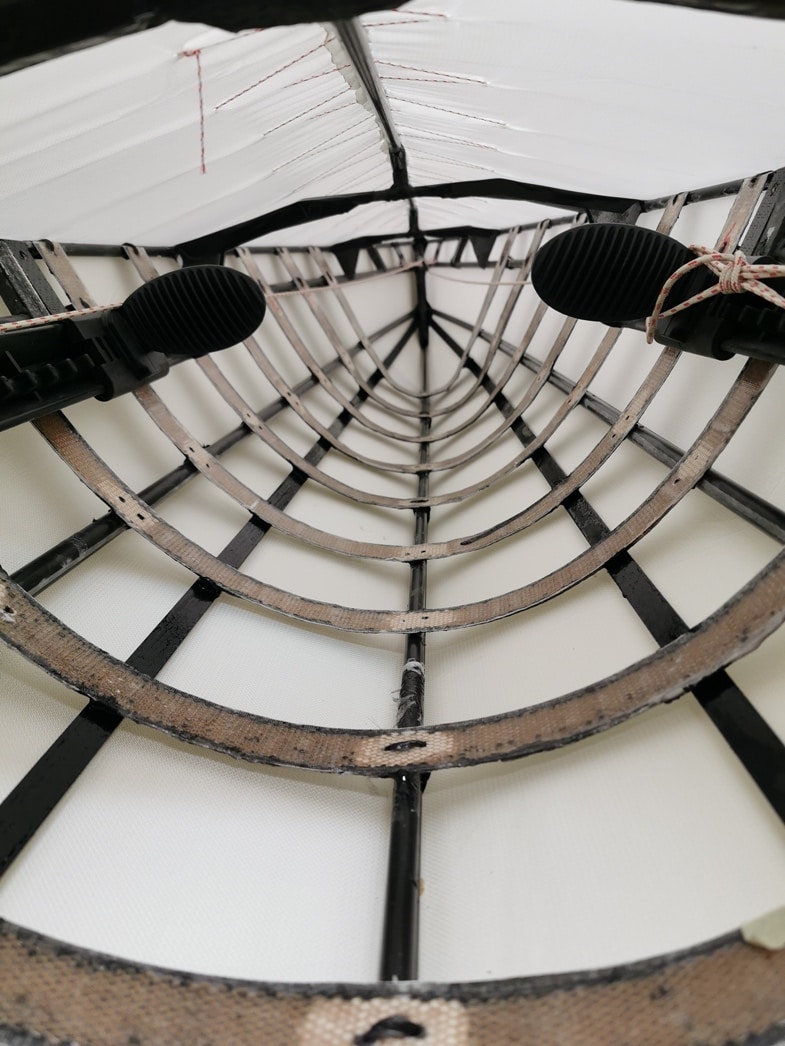
Since that could not be accepted I had to change something. Changing the position of the stringers was not possible since that would lead to destruction of either stringer or ribs. The only way to rescue the work done already was to introduce another pair of stringers laid between the keel and the stringer as designed (see picture above).
This additional stringer was made of red cedar in a dimension of 15x8mm. The position was set that the additional stringer was placed as close to the original designed stringer and to have just enough clearance between ribs and later skin. Later the wood was painted black for optical reasons.
With that change in design I hope not to have done too much of a harm to the way the boat behaves.
All joints form ribs to gunwales were “sewed” feeding a strand of carbon roving though holes (dry), then soaking it in expoxy. Same was done with the joints of ribs with keel and stringers and, of course, where they touch the stems at bow and stern.
The stringer on the fordeck was reduced in height by using a single tube. With small distances at deck beams 1 & 2 it reaches the height as in the original while bent down to the bow stem (thus it is lower there) and bent down at deck beam 3 as well to enable the coaming resting on the beam.

Toggles were made by drilling cross holes into some 20mm carbon tubes and feeding smaller dia carbon tubes into these cross holes.
Backband was done in 1layer of 400g/m2 Carbon (single layer), reinforcements where screwed to the coaming. Then a 5mm Neoprene was glued to it using some slightly thickened epoxy.
Weight of the frame + coaming before sewing was 7,6kg.

Originally, I wanted to use the Nylon and coating system from skinboats.org. Sadly, I could not get response to my order request. To manage my work to be completed over Christmas/New Year I had to go for another sourcing. We will see about the results and the durability. The worst thing that can happen is that at some time earlier than usual I have to reskin the boat.
Before sewing the Kayak all knee-joints etc were taped with black duct tape to cover any
remaining sharp edges (although sanded carefully)
Skinning was done with 420denier, 230g/m2 nylon cordura. It was OK, so far. I got a bit more stretch in the back on one half of the nylon at the seam- leading to some wrinkles on the side of the seam that I stretched more when I corrected that. This happened since my stitches were not completely across and the twine was held a bit in one direction while doing the next stitch. At the fore deck I managed to avoid that.

While skinning 
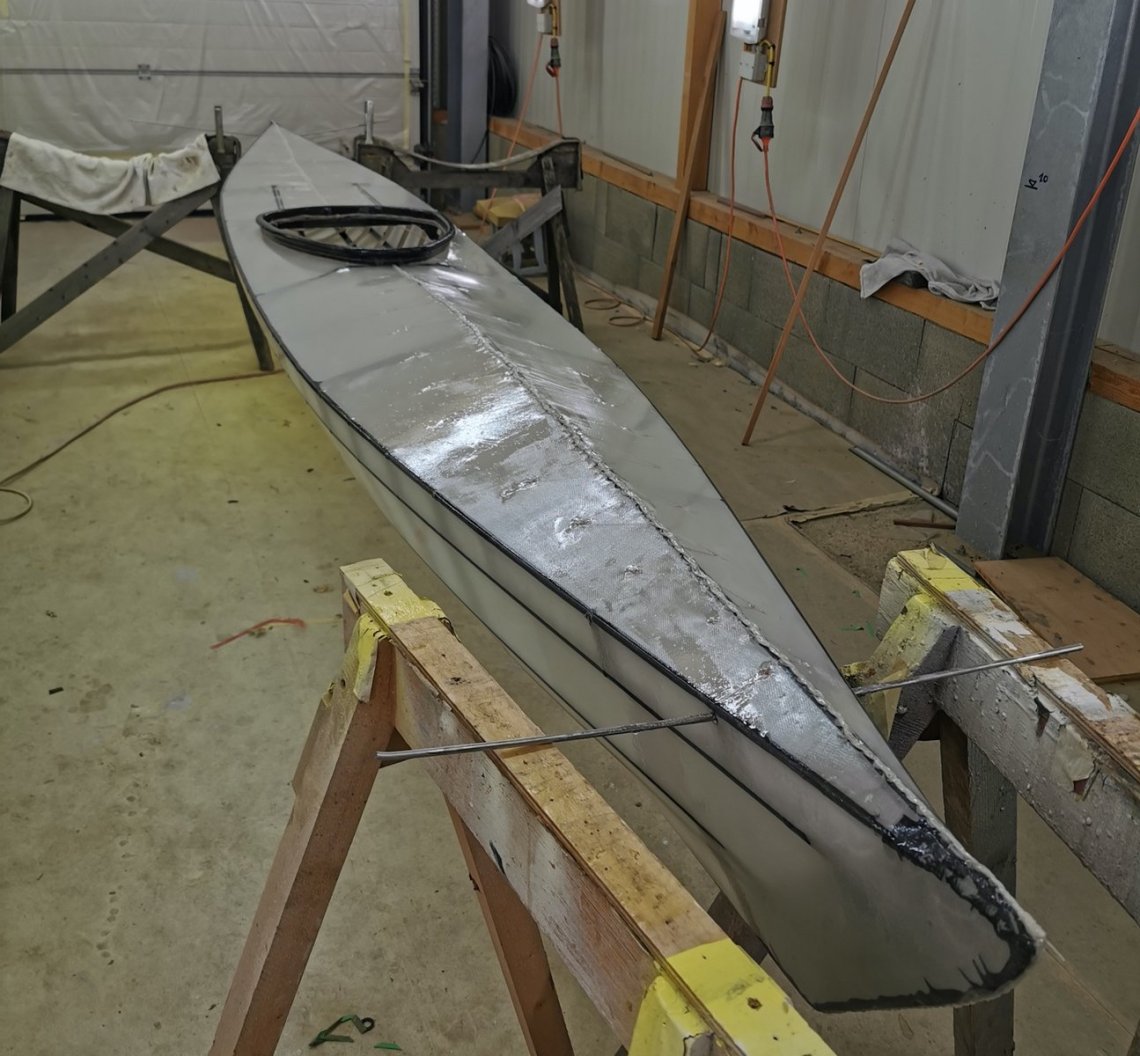
Completed
Coating was done with Lechler Lechsys Isolack 29140 and hardener 29340. In total I used approx. 1200g PU and 600g hardener. I had the hint for that from Franz in Germany who has built his boat with exactly the same PU.
Hull and deck were coated 3 times. The PU tended to form some bubbles from the rolling. These were broken by running a foam brush over it immediately after rolling.
Since I could not screw into keel and stringers as Brian does, I decided to burs small holes using a soldering iron where later the loops would be (the holes in the frame I pre-drilled before skinning).
Because screwing to the keel is not possible, I had to invent something different than the PE rubstrips. After coating I covered the bow and stern in nylon folio (from the kitchen) to protect it, then laminating a strip of 5cm Kevlar over it. The cured Kevlar was then removed and glued to the F1 using a small amount of PU-glue.

Total weight: 9,9kg, including foot braces (Amazon) and back band.
Total working hours: 76h (not including times for finding supplies, recalculating plans etc)
Material cost: € 680, majority for carbon tubes and PU coating (not including material/tools for vacuum bagging since I had that already)


February 20, 2020
Hi Günter,
completely crazy but cool project. I had the same issue with the ribs. I had missed that Brian does not bend them in a smooth curve, but instead they have the main bends in the places where stringers and keel touch. Other than you I could resteam them and get them to the right shape.
Cheers,
Franz
August 12, 2020
Hi,
Really fantastic build. Thanks for sharing. How does it paddle? I suppose you have had some possibilities to do that this summer.
Cheers, Henric
January 25, 2021
Hallo Günther,
Ich bin begeistert. Tolles Boot. Perfekte Arbeit.
Gerne würde ich mit Dir in Kontakt treten. Melde Dich bitte bei Interesse. Lebe nach 30 Jahren in Wien-Umgebung nun in Linz und “gurke” mit einem sehr komfortablen und sicheren Prijon durch die Gegend…
mit besten Grüßen
Gernot